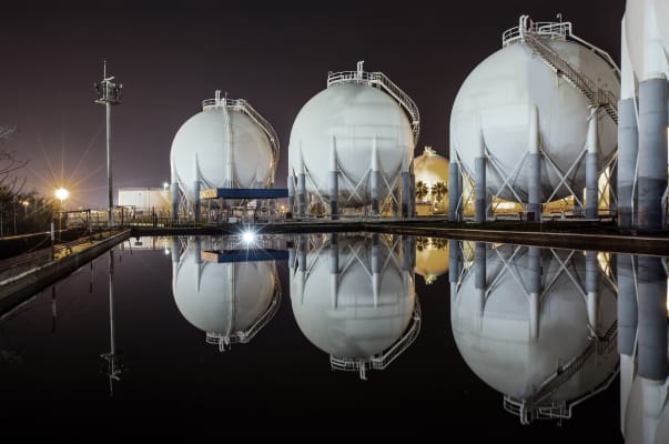
LNG plant
Fire & Gas detection system for LNG plants
The historical safety record for the LNG industry is strong. Engineering, installation and lifetime use takes into account the well known hazards of such an installation. Different levels of protection ensure that potential hazards are discovered and eliminated before they become a major risk to the installation premises and the people working there.
While LNG in its original form is a liquid, it will quickly turn into a vaporized gas upon entering the atmosphere. Potential ignition sources may quickly create a dangerous situation, and thus our goal is to discover any atmospheric presence of gas as early as possible. This is why the detection system becomes an early and important barrier to protect an LNG plant. Detecting potential risks and taking necessary precautions to eliminate or prevent them from escalating is the main objective of the safety system.
Several factors need to be examined in order to make sure that we have a trustworthy system.
Typical detection solution
There are two key factors when considering an F&G detection system: Availability and Reliability. The first is rather self-explanatory – it is important that the detection system (and its functions) is available when needed. The latter is no less important – that we can rely on the system to perform when needed. The first step to ensure we can trust our system is to look at the chain of devices necessary to detect and take appropriate action. A very simplified drawing showing a typical safety system for detection is shown below.’
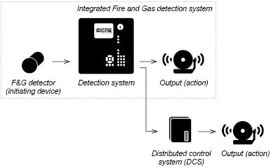
Every scenario (a beginning fire, a gas leak, etc.) can be reported by a detector. The detector is the system’s initiating device, and its performance is crucial to ensure early and reliable detection. We want to detect the incident as early as possible, and at the same time avoid detection and reporting of unwanted or nuisance alarms. Different detectors have different properties, particularly when it comes to performance. Comparing datasheets may cause detectors which perform very different to look almost the same. When consulting manufacturers and suppliers of fire and gas equipment, a good rule of thumb is to always ask what testing has been done according to performance standards (e.g. FM3260 for flame detection). This will point out the differences when it comes to the performance of a specific device. It is of course important that the equipment has the right ingress protection and can withstand necessary environmental conditions, but after all it is the performance of the device that determines whether it will properly detect an incident or not.
The detector will report a detected incident to the detection system. By this, the communication becomes important (type of medium, robustness to EMC and environmental conditions, etc.) to avoid loss or delay in the communication channel. This is also a driving factor to try and utilize a loop or another form of redundancy for the communication between the detector and the system. In a loop, short-circuit isolators will ensure that any detector or cable faults will keep all other devices properly communicating with the system.
The purpose of the detection system itself is also to ensure that any appropriate actions are taken. In an integrated fire and gas detection system, the logic is normally kept in the same system and actions are taken care of by activating outputs to different devices (activating beacons/sounders, closing ventilation/dampers etc). An alternative configuration is as shown in the figure on the left; the detection system passes the alarm on to a Distributed Control System (DCS) which will take care of the needed actions. For the last solution, it is important to highlight the need for a secure communication channel between the two systems. Very often the project will also require redundancy for this type of communication.
Safety and IEC 61508
So how do we consider a communication channel or a detection loop to be safe or not? In installations like an LNG plant, a hazard and operability study (HAZOP) is normally done to identify and evaluate potential problems that may be a risk to people or equipment. This will help us determine what kind of equipment is required to protect the installation; however F&G equipment have different safety ratings that need to be examined as well.
The reliability is important for the entire system and not only single components. A good standard for consideration of system availability and reliability is IEC 61508: Functional Safety of Electrical/Electronic/Programmable Electronic Safety-related Systems. This standard defines what is called “Safety Integrity Level” (SIL), an assessment of reliability, failure to safety (how safe the system is) and management/lifecycle considerations. The SIL tells us something about the probability of a failure on demand, i.e. how likely is it that the system functions as intended the day we actually need it? It can work 10 out of 10 times when tested, but that does not matter if it fails the next time it is supposed to detect a real hazard.
Since we are talking about an entire system with dependencies, it is important that the entire system is evaluated according to this standard, and not only single components one by one. The entire system, from detection by one of the initiating devices to action by one of the outputs, should fulfil the requested level of safety (normally SIL2 is required for an F&G detection system). Combining single components does not necessarily give us the same rating (even if they are rated SIL2 individually). To make sure we can maintain all aspects of IEC 61508, a Safety Analysis Report (SAR) is often done during the project. In order to simplify this and ensure you will maintain the required safety level, you should ask the suppliers to prove compliance of the entire system according to IEC61508. This will ease the projecting of a safety system.
In most cases, an LNG plant is a wide installation with long distances between areas/structures. The installation consists of buildings, process area(s), pipelines and other premises to be protected. By choosing a system which can integrate all types of detection as well as extinguishing, this will provide a significant reduction in the installation cost. The AutroSafe F&G detection system is being applied worldwide in one of the most critical industries, Petrochemical Oil and Gas. Part of the reason for this is that the system maintains a third party verification and certification according to IEC 61508.
Australian LNG Project
In Australia, the system is just introduced and installed on a new LNG project. The project involves 435 kilometres of pipeline linking the gas fields to the main facility, and the construction of an LNG plant for conversion of the gas to LNG for export. The first stage of the project includes two LNG trains (i.e. processing units) with a design lifetime of more than 20 years. The production capacity is more than 8.5 million tonnes of LNG per year (expandable up to 12 million tonnes).
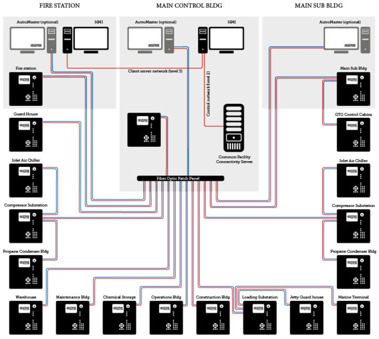
The LNG project is realized by having one AutroSafe F&G detection panel in each building. Due to the long distances between the buildings, all panels are interfaced via a redundant fiber optic network. The figure below shows how the panels interconnect with each other via two independent networks (for redundancy), and with centrally located panels in the Main control building, the Main substation building, and in the Fire station.
Middle Eastern refinery
AutroSafe IFG is also installed at a refinery in the Middle East, a setup which further explores the possibilities of the system. The refinery port is a combination of several self-contained buildings and modules; and all detection and extinguishing equipment are integrated into one AutroSafe F&G detection panel. This includes everything from traditional heat and smoke detection, manual call points, and flame & gas detection, to individual release of separate extinguishing zones inside each building. Early warning aspiration systems (HSSD) are also integrated into the same system (most often considered for local electrical equipment rooms). By combining all the panels into a single plant-wide network, one can easily monitor the entire plant from one or several locations.
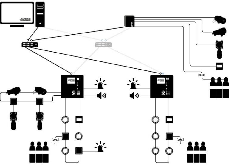
A simplified concept drawing for an installation like the Middle Eastern project is shown on the top of the page. The F&G detection panels interface all types of detectors and take appropriate actions. Communication to a plant-wide DCS is normally done via Modbus or by direct interpretation of the F&G systems communication protocol. In addition, local workstations are located in centralized control rooms and e.g. the local fire station. The function of a setup like this can be decided by the configuration data, as it can either be an independent self-contained system for each building or provide a distributed C&E across the entire plant. The entire system will fulfil a requirement for a SIL2 rating for the complete system.
By using loops for all the field devices, we ensure that any break or short-circuit in the wiring will not influence the performance of the system. Even the flame and gas detectors can be protected from such faults by having them localized on a loop. In the solution above, the same two-wire loop also provides power to the detectors, which can translate to major savings when it comes to installation costs.
F&G detection systems for LNG plants can be realized in different ways; most importantly, we need to consider the safety aspect of the solution. In order to properly accomplish this, we should examine the entire system with all intended functions (e.g. detection from a smoke detector through all communication pathways including the activation of an output module). Only by doing this, can we say something about how safe our system is, and if we are able to maintain the needed safety rating for the system. After all, it is the system performance on that day we need our system to perform 100 percent that becomes critical.
Fire & gas safety in LNG plants
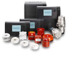
AutroSafe Integrated fire & gas detection system
Our high-end AutroSafe Integrated Fire and Gas detection system provides innovative, flexible and integrated fire safety solutions that can easily be tailored to different applications and needs. Reliable and proven solutions meeting today’s strict requirements and standards within fire safety.
– Advanced technology simplifies service and maintenance, resulting in minimum downtime
– Cost-effective – fast and easy access to spare parts, service and support
– Favorable terms and conditions for service and warranty agreements
Learn more
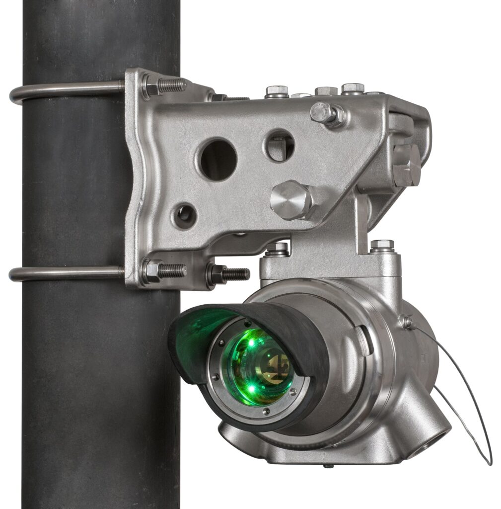
AutroPath – Line-of-sight IR gas detection
Line-of-Sight infrared (LOS IR) gas detectors provide continuous monitoring of combustible hydrocarbon gas concentrations in a wide range (typically, 0 to 5 LFL-meters, over a distance of 5 to 120 meters). They must function under the heavy vibration typical of an industrial site and must endure harsh environments.
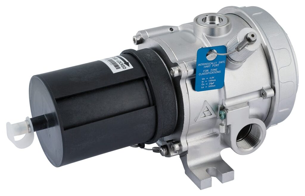
AutroPoint – IR hydrocarbon gas detection
The AutroPoint family of point IR gas detectors lead the industry in quality, performance, and lowest cost of ownership.Across the globe, optical IR gas detection is now the preferred detection technology for early warning of flammable hydrocarbon gas leaks.
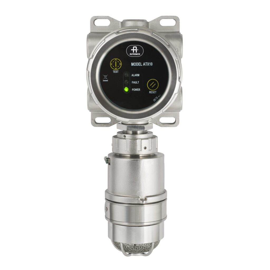
AutroSonic – Acoustic gas detection
The AutroSonic acoustic gas leak detector hears gas leaks that others don’t – the instant they occur. It is the first non-contact gas leak detector of its kind that recognizes unique sound “fingerprints,” analyzing 24 discrete ultrasonic bands, while ignoring nuisance ultrasonic sources.
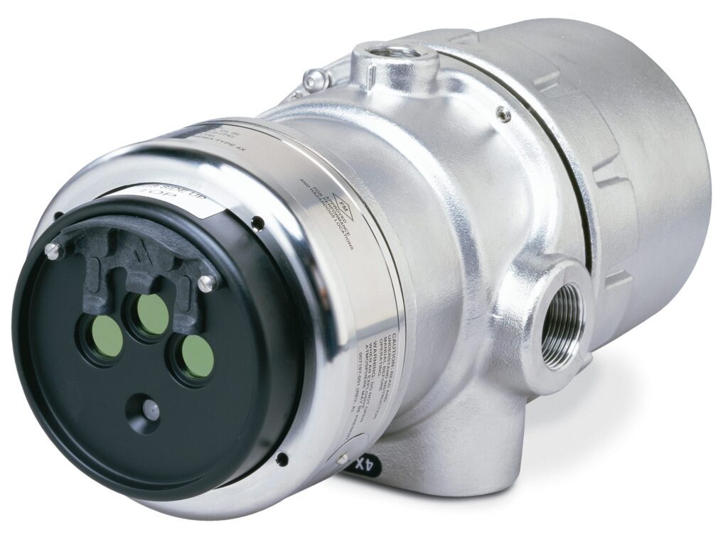
AutroFlame – Multispectrum IR flame detection
Prevent unnecessary costly operational shutdowns with the enhanced X33 multispectrum infrared flame detector. From refineries to turbines, offshore exploration/production to hangars, FPSOs to fuel storage, let the X33 protect your personnel, assets and property